"/>
"/> "/>
"/>RichRap’s know-how of 3D printing and open-source tools for improving the product development of electronics

In the world of 3D printing, I go as RichRap, real name Richard Horne, and I’m the co-author of “3D Printing for Dummies” and designer of multiple open-source 3D printers under the RepRap project. I’ve been blogging for over 10 years about 3D printing and created the MasterSpool standard for reusable filament coils that eliminates the need to use single-use plastic spools. My day-to-day work is in the electronics design and manufacturing sector, where I produce embedded, industrial, and consumer products and provide design consultancy for clients around the world.
Before computers became commonplace, electronics layouts and electronic components were manually designed by using effectively ‘masking tape’ on large drafting sheets of transparent film. These film masters were photographically shrunk down to produce the circuit boards and a similar process produced the silicon chips used in computers and components of early electronic products.
Luckily, I started designing electronics products 30 years ago, just as the first PC DOS-based layout tools were introduced. Fundamentally, the digital design process and use of computer-based tools have not radically changed over all this time, producing the electronic output files required for manufacturing.
An electronic schematic layout is still required to connect components and devices; this is what produces a set of output connection nets that define how the printed circuit board (PCB) will be designed and routed. Many software tools and open source projects are readily available for this purpose, such as commonly used Eagle, KiCad, or subscription-based design software like Altium Designer and Fusion360.
What’s really changed and improved dramatically over the last few decades is the ability to produce 3D visualizations of components and design entire products on the computer before starting any physical tooling or manufacturing.
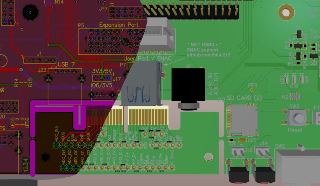
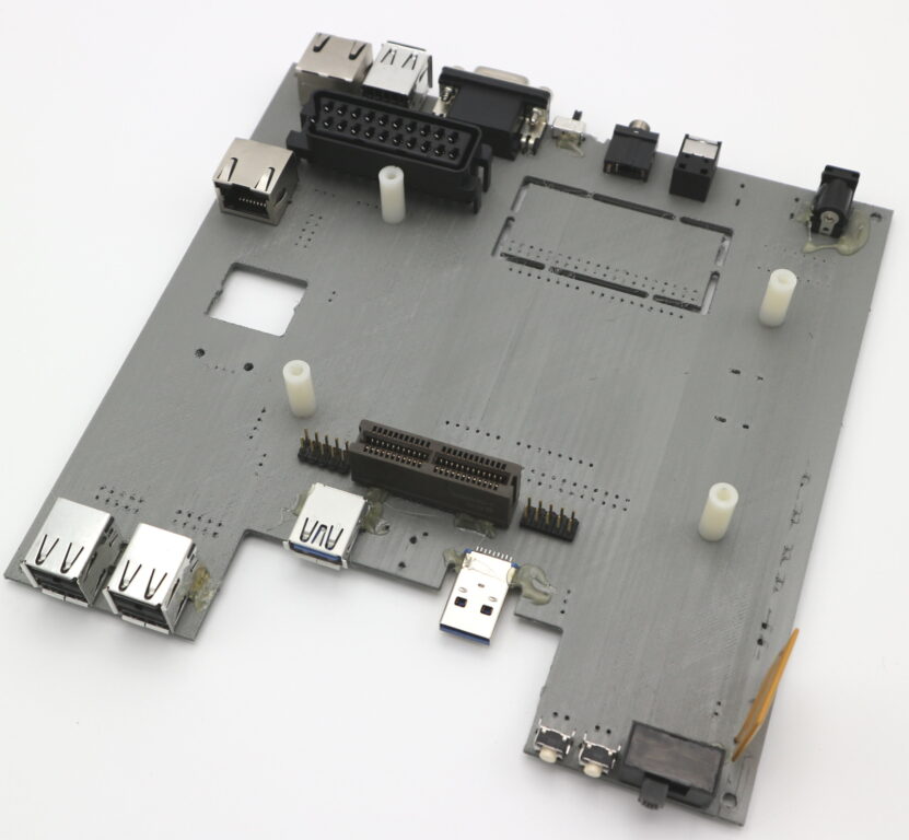
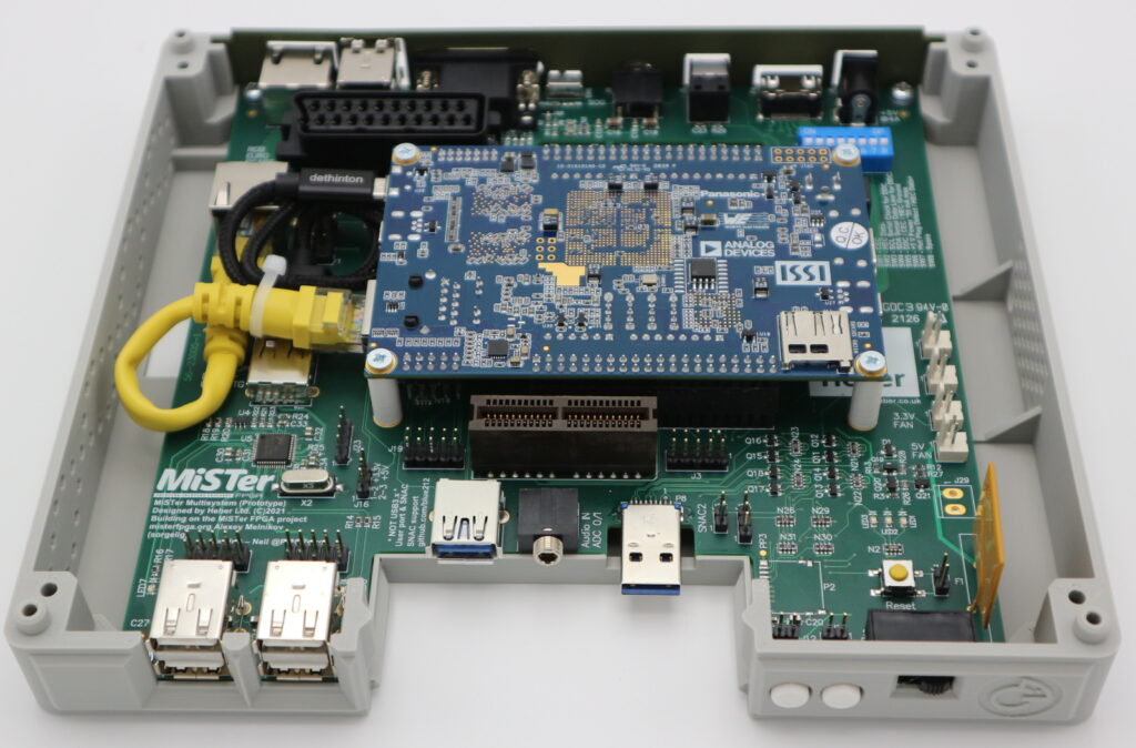
We can now export a 3D model of a new electronic control board with ease and at any point during the design process. This gives us the ability to both see the virtual product and produce a physical model with the use of 3D printing. These 3D files and prototypes are often used to show examples to an end customer or to continue to further the design of enclosures and manufacturing tooling.
Any process that allows you to rapidly try out ideas and concepts and can take you from prototyping all the way to the final product, opens up opportunities for creativity and innovation. Desktop 3D printing has been one of the most significant enablers for innovation, development, and manufacturing in the past decade.
Looking back, the most significant change in product development has been the speed of rapid prototyping and automated manufacturing. 3D printing has been used in industry since the mid-1980s but only in recent years have highly accurate desktop 3D printers become common to see and use in offices and homes.
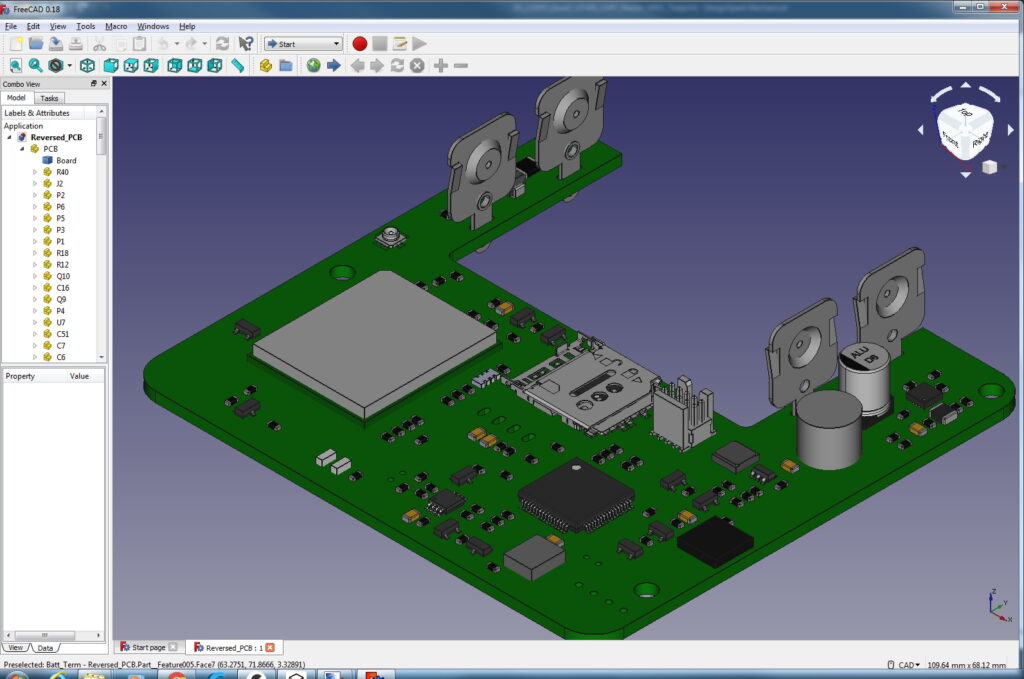
Manipulating 3D models has never been easier. Open-source software such as FreeCAD and OpenSCAD allows powerful solid model and parametric design processes, along with common import and export formats.
Exporting a 3D prototype PCB design into a 3D printing slicer allows you to create an accurate physical model in hours.
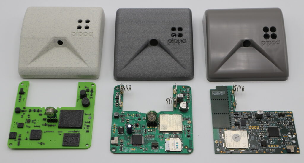
These advancements in low cost and accurate 3D printing make it possible to manufacture an entire product without costly tooling or significant production delays. This groundswell of ongoing process automation has also been driving forward the manufacturing 4.0 revolution for mass industry. These incremental advancements and affordable desktop manufacturing systems also allow smaller niche sectors of individual product customization, where a product run of 1 bespoke unit is a unique and viable option.
Top tips for in-house product design and development
Get your own desktop 3D printers. While it can be viable to use a 3D print bureau to manufacture samples, having your own set of desktop 3D printers allows immediate testing and iteration. Let the machines do the hard work, help you to innovate, save you money and reduce development times. You don’t need to invest in a multi-machine ‘print farm’; a few desktop machines can do wonders for creativity. While it’s true that some maintenance is required and you will need to learn a few new software skills, nothing beats the ability to be in control of your own prototype production and gain an understanding of the materials and constraints of the 3D printing process.
Design for the 3D print process
Trying to force a design intended to be tooled up and injection molded for it to be 3D printable is often not a good starting point for innovation and rapid prototype testing.
It’s important to always consider the end requirements for tooling, and that a viable 3D print design is also required during the development process. You don’t want to be removing masses of support material and spending hours sanding and smoothing down every model. A few changes to a design can result in easier 3D printing and a faster iteration of the idea for your specific customer or purpose.
Work with overhangs
Adding a 45-degree angle to a feature can stop the need for support material generation.
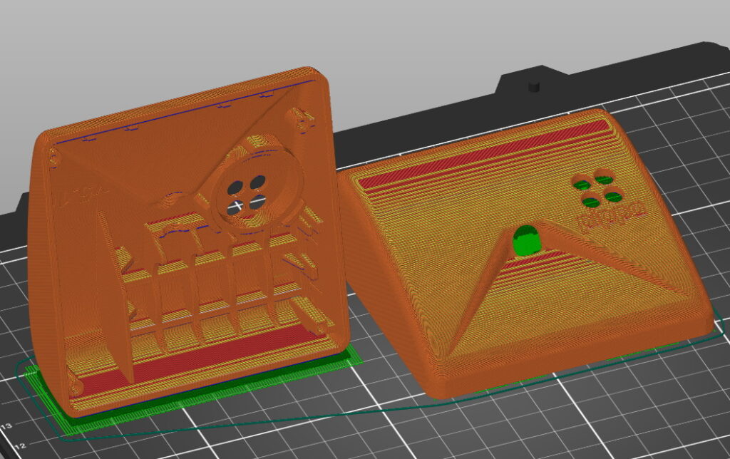
Consider print orientation
You may want a perfectly smooth finish on the outside of your 3D model, but for a product enclosure that could entail the use of a lot of support material. Adding a flat base and orientating a model at a vertical angle can often give a higher quality finish and significantly reduce the need for support material.
Make easy-to-use prototypes that look professional
Using a matte material can give a quality finish to an FDM 3D print, help hide any layer lines and photographs well.
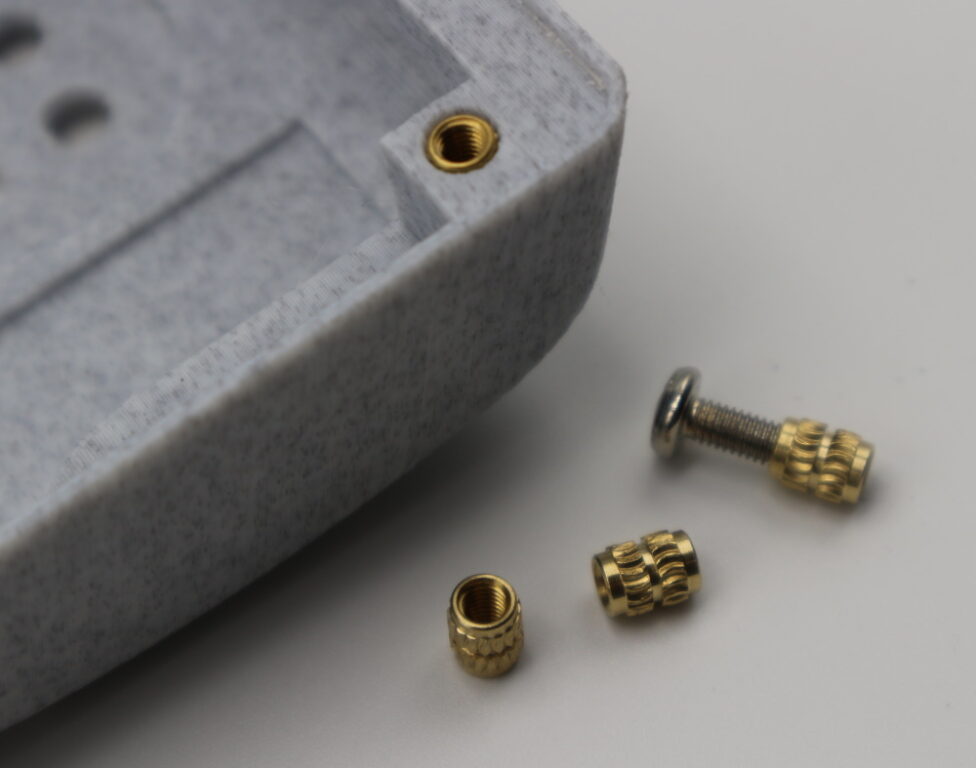
Consider using threaded heat inserts in your 3D print models. This will make the demonstration easier and allow for more experimentation during the design and testing phases.
If you need a smooth look, consider post-processing. Sanding and filling can smooth out layer lines, and PVB materials can be chemically smoothed.
Understand changes needed for tooling and injection molding
It’s unlikely that your 3D model is going to be viable for injection molding without a few changes to the design. Consider this early on in your design process, but also remember to follow the design for the 3D printing process and consider how it will need to change to allow for volume manufacturing.
If you need assistance, work with a tooling company for advice during the design stages. For example, Protolabs in the UK will assist you with required changes for draft angles, minimum feature size, plastic material choices, and the required finish of the injection-molded product.
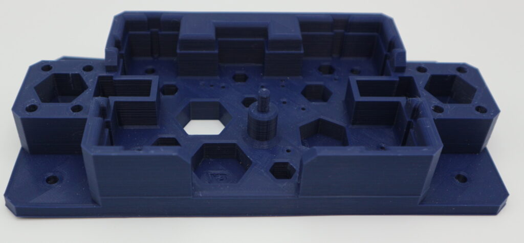
Consider 3D printing your own production tooling
We now routinely produce all the first pre-production batch tooling with 3D printers. This allows for rapid testing, programming, and small-batch manufacturing without expensive tooling costs for text fixtures and custom programming equipment, until you can finalize the design.
Making a fixture to test and program embedded software into new electronics is really very straightforward:
- Export the bare PCB file into a 3D CAD program like FreeCAD or Fusion360
- Use the test-pad points, pin location, and connectors as location points for sprung gold test pins
- Extrude a shape to hold the assembled PCB board – considering any connection of the top, connectors, or components fitted to the board.
- Add a set of clamps to the design
- 3D print the fixture and populate it with test pins, programming equipment, and any other electronics needed for unit testing.
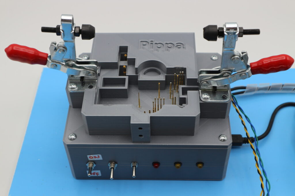
This will allow you to quickly get products into pre-production testing and, if volumes justify the investment, prepare for ordering a full functional set of automatic test equipment.
If you would like to hear more tips and advice for the use of 3D printing, check out my blog and YouTube channel or follow me on Twitter at @RichRap3D.