"/>
"/> "/>
"/>New drivers for the motors
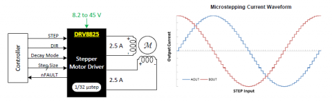
At RepRapBCN we always try to improve the printer on an ongoing basis and that is why today we bring a new change that we believe will improve the reliability of your printer. We decided to change stepper motors drivers for more powerful and robust ones. They are the Pololu DRV8825.
Improvements
These drivers are based on the DRV8825 chip from Ti and show a number of advantages over the previous ones.
- The calibration potentiometer is single turn and much better quality, allowing more precise adjustments and fewer breakages.
- According to specifications, this integrated circuit can supply up to 2.2A with proper cooling, a substantial improvement over previous drivers. More than enough for our application.
- This driver can deliver higher resolution thanks to its 1/32 micro stepping. For more information go to the advanced mode section below.
- Increased power dissipation. First by the type of encapsulation and second by the design of printed circuit board. There’s no need of heatsink.
- Greater motor voltage supply up to 45V (35V old ones). At first, glance seems useless because we have a fixed 12V power supply, but this feature allows the drivers to be more resistant to possible LC spikes produced by the system.
- They are purple!
We believe those are reasonable grounds to make a change, resulting in fewer errors and fewer headaches for everyone.
Replacement and Calibration
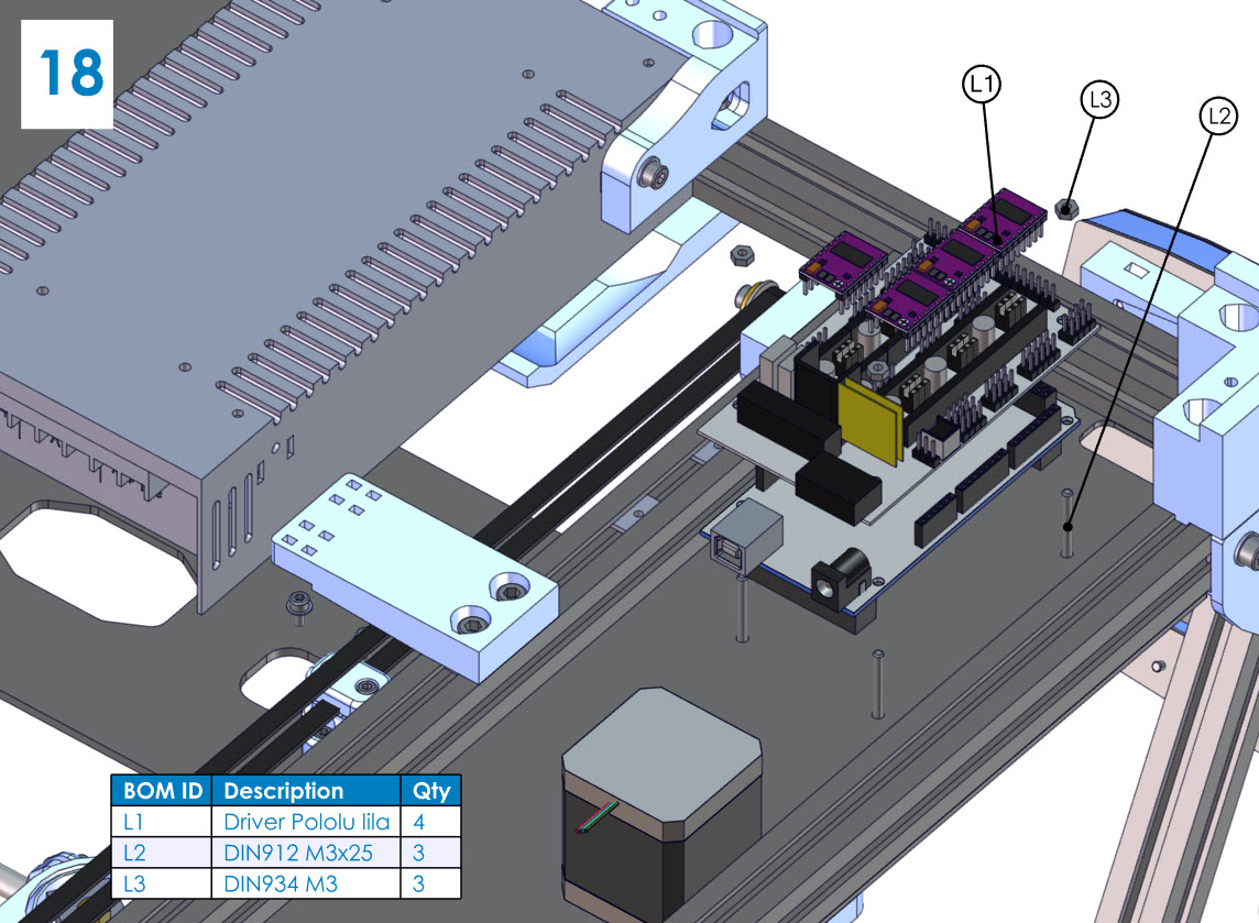
Whether you need to replace a faulty driver or update your old drivers, you have to follow these simple steps.
You simply have to remove the old drivers (white), extract two jumpers on the RAMPS electronic board and place the new driver (purple) in the correct orientation. As a picture is worth a thousand words, below you can see the jumpers that need to be removed. Removing these jumpers make the new drivers totally compatible with previous ones, avoiding making any additional changes.

Next, we are going to describe how to regulate the drivers correctly in order to provide the necessary power to the motors to run everything smoothly without overheating.
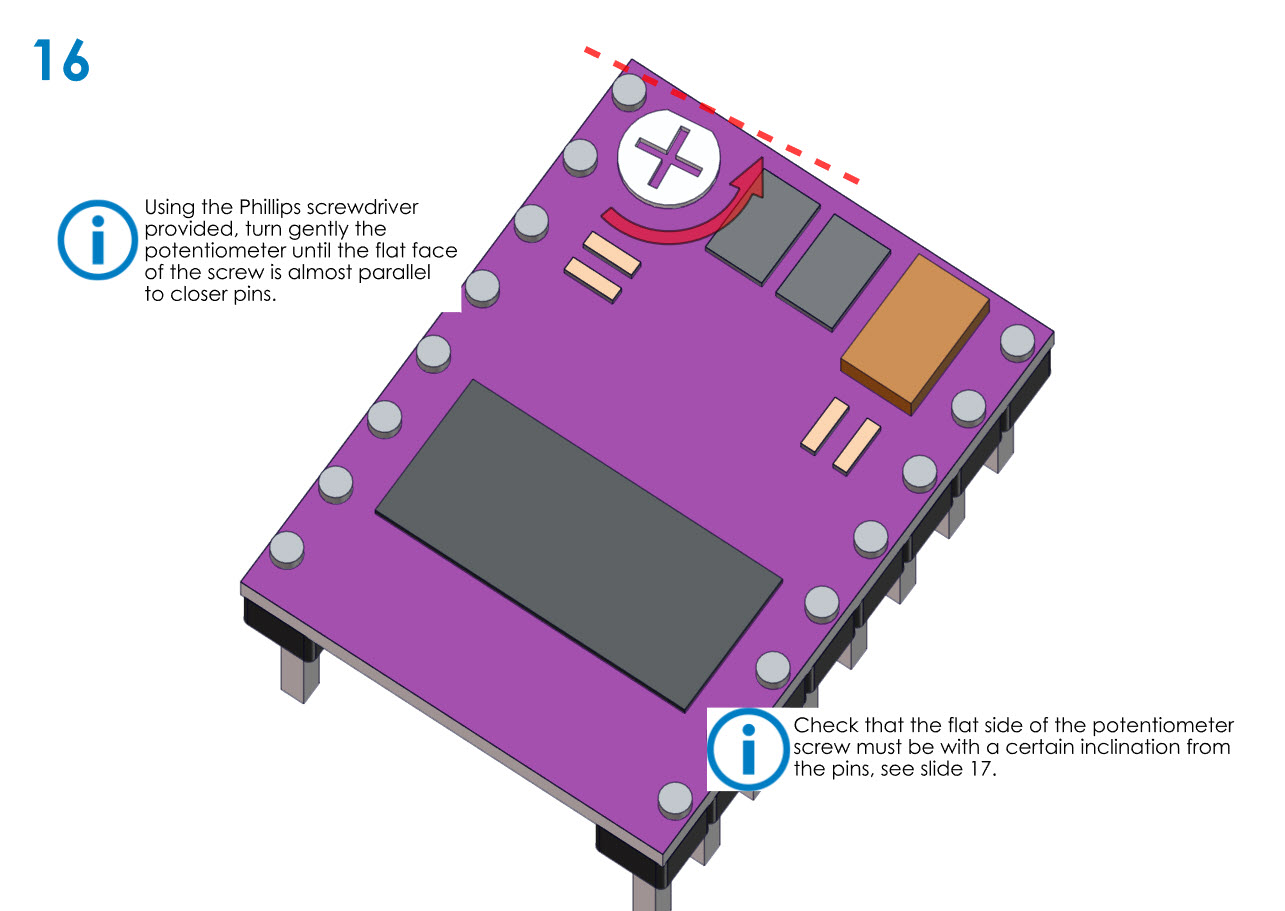
The drivers are regulated by a small potentiometer placed at one end. If we rotate clockwise, power is increased and counterclockwise decreases. By factory default, they come poorly regulated and, therefore, is a good practice to put in some time to make a proper calibration. If we replace them as they come, we face the risk of delivering too much power to the stepper motors and we can get ourselves burn.
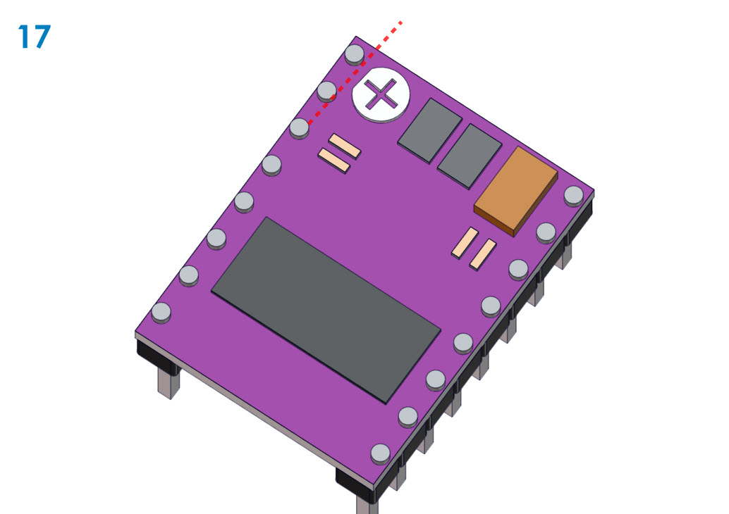
In the picture, you can see that the potentiometer has a small chamfer on the head (flat side). We have experienced that orienting the flat side up, the driver gets quite well calibrated without a multimeter or tester.
For the more “experienced / theoretical” users is possible to calibrate the drivers with a tester. To do so, please read this article before in the RepRapWiki. There’s need to say that we must be careful not to cause any short because there is a risk of damaging any electronic component.
Advanced mode
For those who want to go a step further, we propose squeezing the key feature of these drivers, the micro stepping.
The micro stepping is simply a technique to increase the resolution of a stepper motor making the steps smaller and smaller. This is achieved by exciting the coils progressively so that the movement is as continuous as possible (although the steps are discrete). Thus, if our motors are 1.8°/step without micro stepping with 1/32 micro stepping these steps become of 0.056º/step.
Below you can see a comparison chart between the micro stepping and resolution of the X and Y axes of BCN3D+. Also, you can find the steps/mm for all the axis and configurations. For Z axis would simply take into account the pitch of the 8mm threaded rod.
With a smaller micro stepping we get more resolution and movements will become more fluid and continuous (although we are not able to appreciate them), but not all are advantages because now the microcontroller will need to provide double number of pulses to move the same distance (remember that every step now travels less distance) and this may affect the maximum speed of the printer. It is for this reason that we need to reset the values of steps per millimeter for each axis in the firmware.
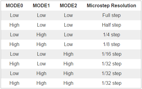
So, in this case, is not necessary to remove the jumpers. The jumpers allow us to select in which mode of micro stepping our driver works. They are simply chip pins that depending whether they are at a high or low level a micro stepping mode is selected. In the following table, we can verify that if all jumpers are HIGH/HIGH/HIGH would be in the case of a 1/32 micro stepping.
To configure the step/mm in the firmware we have three options:
- Display mode: If we go to Menu>Control>Motion> Xsteps/mm, Ysteps/mm, Zsteps/mm, Esteps/mm We must adjust the values for each axis that the driver have been changed to twice the current value. Next, in order to keep the values when you turn off the machine, select the Store memory option in Menu> Control. The values can be found in section 2.
- Arduino IDE: We need to open the firmware with the Arduino IDE and go to the
Configuration.h tab and locate the line 353.
#define DEFAULT_AXIS_STEPS_PER_UNIT { 80.19, 80.43, 2560, 458.3 }These values define the steps needed to travel a unit of distance. We just have to modify them multiplying by 2. Therefore,
would be something like this:
#define DEFAULT_AXIS_STEPS_PER_UNIT { 160.38, 916.6, 5120, 458.3 } - USB: We need a program to open a serial communication with the printer via USB. Once the connection is established send the following g-codes that allow us to change the values we are looking for.
M501 //Reading the values stored in the EEPRO MM92 X160.38 Y160.86 Z5120 E916.6 //Modifying the Step/mm values for each axis M500 //Storing the new values in the EEPROM M501 //Checking if the values have been stored properly
We hope this article is useful and we are looking forward to hearing your comments. Any suggestions will be welcomed.